PROTECT FUSE user’s guide

WHAT IS THE HINODE PROTECT FUSE?

All means of protection adopted on design may become futile in cases such as: Errors in assembly work Contamination with a foreign substance Damage to semiconductors by disturbances such as heat or shock Before such accidents affect other chips or equipment, HINODE PROTECT FUSE will safely block off equipment as the last line of protection.

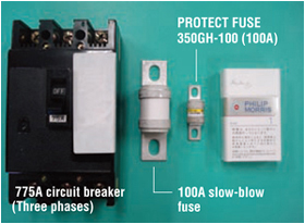
HINODE PROTECT FUSE is a fast-acting fuse that blocks off equipment in a few microseconds even in cases of short-circuit accidents that ordinary fuses (slow-blow fuses) and circuit breakers cannot protect against.

FEATURE OF HINODE PROTECT FUSE

  • Safe and reliable: Fast-acting fuse that can block off even direct-current
  • Small and compact: Compared with a slow-blow fuse and a circuit breaker (see photo )
  • Applicable to high voltage: Up to 1500V*
  • Large capacity: Current breaking capacity of up to 100kA*

    * Specifications vary depending on the product; refer to the specifications of each product for details.

FEATURE OF HINODE PROTECT FUSE

HINODE PROTECT FUSE is widely used for general power electric products (approximately 1kW), including:

  • Inverter motor drivers
  • Servo drivers
  • Direct-Current power sources
  • Alternating-Current variable power sources
  • Uninterruptible power supplies (UPSs)

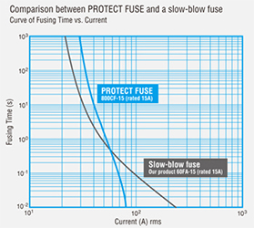
Q : Is HINODE PROTECT FUSE easy to break if it is so quick to cut off?

A : No, it’s not. Conversely, around the rated amperage, our fuse is less likely to break than a slow-blow fuse (refer to chart below).

WHERE IN THE CIRCUIT SHOULD I USE A FUSE?

First, consider what you would like to protect with the fuse.
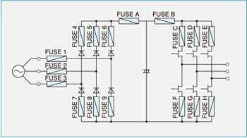
Examples of applying position on the inverter circuit

TO PREVENT SECONDARY DAMAGE TO SUPPLIED POWER

  • To protect from condenser short circuit or IGBT short circuit … Applicable to FUSE A
  • To cope with accidents from condenser short circuit, IGBT short circuit, and diode short circuit … Applicable to FUSE 1 and 3.
  • To cope with condenser short circuit, IGBT short circuit, diode short circuit, earth short circuit … Applicable to FUSE 1, 2, and 3, and also to FUSE 4, 5, 6, 7, 8, and 9.

TO PREVENT DIODE CHIPS FROM BEING DAMAGED

If you would like to prevent explosion or ignition of chips with fewer fuses:

  • To prevent damage to a chip by adverse DC current … Applicable to FUSE A.
  • To prevent damage to a chip by supplied power current … Applicable to FUSE 1 and 3.
  • To prevent both of the above … Applicable to FUSE A, 1, and 3.
  • If you would like to reuse sound chips as well as to prevent explosion or ignition of chips …Applicable to FUSE 4, 5, 6, 7, 8, and 9.

TO PREVENT EXPLOSION AND SHORT-CIRCUIT MODE OF IGBT OR THYRISTOR CHIPS

  • If you would like to protect with fewer fuses … Applicable to FUSE B.
  • If you would like to reuse sound chips (only for thyristors) … Applicable to FUSE C, D, E, F, G, and H.\,
    For devices from a few kilowatts to tens of kilowatts, fuses are often applied to FUSE 1, 3, and A.

HOW TO SELECT THE RIGHT FUSES

MAIN FACTORS IN SELECTION

  • Working voltage (AC or DC)
  • Normal electric current
  • Inrush current
  • Ambient temperature
  • Breaking current (maximum breaking current and minimum breaking current)
  • Durability performance
  • Installation structure

Select an appropriate fuse taking these factors into consideration.

WORKING VOLTAGE

  • Set the rated voltage of the fuse over the voltage of the circuit where the fuse is to be inserted.

NORMAL ELECTRIC CURRENT

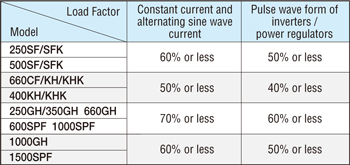
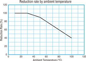
* The load factor is at the ambient temperature of 25°C.

  • To avoid unnecessary fusing, lower the load factor of the normal electric current according to the rated amperage of the fuse. The main load factors used for our products are as follows:

INRUSH CURRENT (WHEN CONSIDERING FUSING L2T)

  • The fusing l2t indicated in this catalog is the energy of the fused electric current in time when the heat that occurred does not radiate from the inner conductor by heat conduction.
    The fusing l2t varies according to fuse types. The fusing l2t has to be considered if the Inrush current (surge electric current, start electric current, plunge electric current, and so on) occurs.
    If the l2t of the Inrush current is higher than the fuse l2t, it will cause unnecessary fusing.
    By setting the l2t of Inrush current to less than 25% of the fuse’s l2t, the fuse will withstand the repetitive Inrush current over 30,000 times.

AMBIENT TEMPERATURE

  • The fuse characteristics described above assume an ambient temperature of 25°C.
    At a higher ambient temperature, the fuse works in a hotter state, and therefore its life will be shorter.
    If the ambient temperature is high, reduce the load factor.
    (Refer to chart titled “reduction rate by the ambient temperature.”).

BREAKING CURRENT

Maximum breaking current
Assume that the current breaking capacity of the fuse is greater than the maximum broken current of the circuit.
Minimum breaking current
Use the fuse with other protection equipment as there may be a possibility of a restrike arc after fusing if an accidental current in the circuit is below the minimum breaking current.
Circuit time constant
When using for a direct-current circuit, use it under the time constant prescribed by the breaking capacity (or reduce the voltage by its circuit time constant).

PURPOSE AND APPLICATION

When a short circuit occurs, an overcurrent*1 greatly exceeding the rated amperage flows in a circuit.
This causes abnormal heat generation on the wiring pattern and parts and may lead to an accident such as ignition, fumes, or explosion. When a short-circuit current damages a component, it is generally not easy to locate, so restoration of functionality tends to take a long time.
Our fuses will help minimize such accidents and, in the case of an accident, will help you work efficiently for restoring the functionality*2. The following are applications of our fuses:

PROTECTING SEMICONDUCTORS(DIODES, THYRISTORS, ETC.)

PURPOSE
To protect semiconductors from the overcurrent when a load circuit shorts out or to prevent secondary damage when a semiconductor itself is broken down.*3
APPLICATIONS
Thyristor stacks, electric power regulators, electric furnaces (equipment with heater controls by SSR, etc.), DC stabilized power supplies, and, generally, modules with a power device.

PROTECTION FROM A SHORT-CIRCUIT MODE(ARM SHORT CIRCUIT) IN AN INVERTER CIRCUIT

PURPOSE
To prevent secondary damage of an arm short circuit caused by destruction of a transistor or a diode, a breakdown of a control circuit and/or a drive circuit, or a malfunction by noise.
APPLICATIONS
Bridge circuits in equipment (motor drives, air conditioners, UPSs, etc.) with an insulated gate bipolar transistor (IGBT) or other related  semiconductors.

PROTECTION FROM A SHORT CIRCUIT CAUSED BY DETERIORATION OF COMPONENTS

PURPOSE
To prevent secondary damage from an internal short circuit caused by a decrease of insulation resistance that is the result of deterioration of a condenser.
APPLICATIONS
Capacitors and circuits using smoothing condensers (such as power supply circuits).

PROTECTION FROM ANY OTHER SHORT CIRCUITS SUCH AS OUTPUT SHORT CIRCUITS, EARTH SHORT CIRCUITS, AND BATTERY SHORT CIRCUITS

PURPOSE
To prevent secondary damage of an output short circuit or an earth short circuit caused by miswiring, an insulation defect of a load, etc. To protect between devices or between units. To prevent secondary damage caused by a two-polar-plate short circuit of a battery.
APPLICATIONS
All industrial equipment such as battery-powered machinery (forklifts, golf carts, UPSs, etc.), control boards, instruments to manufacture semiconductors, and so on.
  1. *1 Short current depends on the capacity of the circuit, but it could be a large current above a few thousand amperes. Most of our products have a current-breaking capacity of over 10kA at the maximum and are able safely to block off such current.
  2. *2 Because of cut-off by a fuse, it is easy to locate the troubled circuit and also to minimize damage to other devices.
  3. *3 The breakdown of semiconductors is caused by diode destruction, gate destruction, temperature destruction, avalanche destruction, oscillation destruction, and so on.

QUESTION AND ANSWERS

I'D LIKE TO KNOW WHICH FUSE TO USE.

Refer to page 30 of PROTECT FUSE USER’S GUIDE.
Fuses need to have two opposing functions: breaking performance (the lower the rated amperage against conduction current, the better) and durability (the higher the rated amperage against conduction current, the better). Select a fuse that strikes a good balance between those two according to your needs.

WHAT SHOULD I DO WHEN ALL FUSES SEEM TO BE UNSUITABLE?

Do not hesitate to contact our office. The data of each fuse and the guidelines on how to choose them listed in this catalog have margins for simplification. We are ready to provide you with more detailed information.
Also, if you could provide us with details of your situation, we would be delighted to help you determine the best product for your needs.

I'D LIKE TO KNOW THE WITHSTAND OLTAGE PERFORMANCE.

Refer to each rated voltage shown on the product pages. Select a fuse with a larger rated frequency than the circuit voltage (for DC, voltage after rectification) on the short circuit expected in case of an accident.
Take the following points into consideration:

  • Keep in mind that rated voltage of a fuse differs between AC and DC.
  • For DC, available voltage changes according to the time constant (L/R) on the short circuit.
    Refer to the chart titled “Application to direct-current circuit” on each product page.
  • Depending on the standard observed (UL standard, CCC standard, etc.), the rated voltage may change.
    Be aware that the fuse may not be regarded as an approved fuse when used in a circuit exceeding the rated voltage.
  • Block-off can be achieved with a fuse that you select by following the above instructions. However, adopting a fuse with more voltage as leeway will enable you to;
    • Cope with voltage fluctuation.
    • Shorten the breaking time (mentioned below).
    • Decrease the minimum breaking current.

I'D LIKE TO KNOW THE BREAKING PERFORMANCE.

I’d like to know if the fuse can block off before the object under protection is damaged.

    1. (a) Refer to the fusing characteristics curve. If the current (A) vs. time (s) curve of the fracture characteristics of the target object is positioned to the right of the fusing characteristics curve of the product, it means the fuse can block off before the object is damaged.
    1. (a) Compensate the shutdown l2t value of each fuse using “shutdown l2t against the working voltage” chart.
    2. (b) If the permissible l2t value for the target object is available, compare the shutdown l2t with it, and if the shutdown l2t is smaller than the permissible l2t value, it means the fuse can block off before the object is damaged.
    3. (c) If only the damaging current vs. time curve of the target object is available, calculate its permissible l2t value [ = (damaging current)2 × time ] and compare in the same way as in (b).

For the area of (1), it appears to be protected by other protection equipment and/or current-limiting functions, and our fuses are often selected emphasizing protecting the area of (2).
Also, even in cases that the shutdown l2t is larger than permissible l2t, our fuses are often used to prevent explosions, ignitions, and secondary damage.

  • I’d like to know the current value that the fuse cannot block off.
    • Refer to the breaking capacity of each fuse. Electric current exceeding the value cannot be blocked off.
    • Refer to the minimum breaking current of each fuse. Electric current below this value cannot be blocked off. Despite fusing, block-off may not take place, possibly causing an accident. Therefore, take the following measures:
  • Using the current control function of the circuits of other protection devices, ensure that current does not flow in that area.
  • Use a fuse with a rated voltage above the circuit voltage to reduce the minimum breaking current.

I'D LIKE TO KNOW THE ELECTRIC DURABILITY PERFORMANCE.

  • I’d like to know the maximum magnitude (amperes) and the maximum rate of increase of overcurrent that a fuse can endure.
    ◇Read the value from the fusing characteristics curve of each fuse.
    ◇When an electric current larger than current range of a fusing characteristics curve flows, the value is calculated from the fusing l2t value of each fuse.

[Fusing time = fusing l2t value ÷ (short-circuit current value)2]

(The fusing time and electric current are effective for overcurrent only once. Once such an overcurrent flows, the fuse becomes easy to cut off.
For more details, refer to the material about life expectancy).

  • I’d like to know the life expectancy of the fuse against constant electric current and repetitive overcurrent.
    →Refer to separate materials for details.

I'D LIKE TO KNOW AN ENVIRONMENTAL RESISTANCE PERFORMANCE.

  • Heat generation: Refer to the temperature characteristics chart of each fuse.
  • Temperature characteristics: Refer to the chart titled “Compensation by ambient temperature.”
  • Other details on environmental résistance: Contact us for more information.

I'D LIKE TO PURCHASE A PROTECT FUSE.

Consult your agent or our company directly any time. If you already know which fuse to purchase, ask for an estimate from our website (http://www.hinodedenki.co.jp/).

I'D LIKE TO ASK FOR ANALYSIS OF ACUT-OFF FUSE.

Consult your agent or our company any time.

  • *Characteristics of each fuse (fusing characteristics, l2t value, etc.)
    indicated in this catalog are average values and may change according to its condition of use, its environmental condition, individual variability, and so on. Use sufficient margin when making a selection.

FOR SAFE USE / PRODUCT WARRANTY

CAUTION!

  • Installation/removal, wiring work, maintenance, and inspection must be done by an expert.
  • Do not use under an abnormal environment such as a place with high temperature and/or high humidity, a dusty place, a place filled with corrosive gas, or a place that may be subject to physical vibrations and/or shock.
  • Do not expose to any liquids.
  • Make sure that the terminal is securely tightened. Using a loose terminal may cause a fire.
  • Use a wire suitable for the working voltage and the conduction current.
    Do not dismantle or remodel the product.When it is used with incomplete wiring, it may cause a fire.
  • Do not dismantle or remodel the product.
  • Do not use the fuse if you find any damage or alterations while unpacking.
  • Use below the rated voltage of the fuse. If exceeded, a burnout or an explosion may occur.
  • Use the fuse such that its current breaking capacity is not exceeded. If exceeded, a burnout or an explosion may occur.
  • When using for the following equipment or purposes, consult our business desk and finalize specifications for delivery. Safety and security in desigh and use are the user's responsibility.
    • Use on equipment or for a purpose that may directly result in injury or death such as medical equipment.
    • Use on a train, an elevator, and so on that may endanger human lives.
    • Use on equipment or use for purposes that may involve a shock or a vibration, such as when loading on a vehicle or a ship.
    • Use on equipment or for purposes that may have a serious effect on society and/or public (e.g., in a traffic system).
    • Use on equipment or use for purposes related to the above.

WARNING

  • When using the fuse for a direct-current circuit, use it at a value lower than the time constant corresponding to the breaking capacity (or reduce the voltage by varying the circuit time constant). It may cause a burnout or an explosion if the time constant of the fuse is exceeded.
  • When there is a possibility of block-off below the minimum breaking current, take measures such as using other means of protection in addition to the fuse. When no measures are taken, it may cause a burnout or an explosion.
  • When the fuse blocks off, the welding arc voltage occurs between the fuse poles, so be sufficiently careful about arrangement of parts around the fuse.
  • A fuse protecting a semiconductor becomes hotter than other general parts even under normal conditions.
    Touching the fuse may cause burns when the equipment is turned on or after an accidental block-off; attach a label to call attention to the high temperature near the fuse installed on the equipment.

DANGER

  • Be careful not to touch a fuse by hand when an electric current is flowing; it may cause an electric shock.
    When installing the product on equipment, make sure that a shock-guard protector is attached to the fuse or a label is put nearby to indicate the danger of electric shock.